Turn-Mill Machining: Questions About the Process
Map the part features and identify setups that can really be removed
Turn-mill machining combines turned geometry with selected milling, drilling and tapping in a turning setup. This page focuses on process planning and finished-part flow, while the companion mill-turn guide covers machine capability selection.
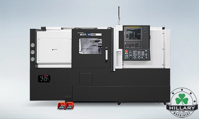
What is turn-mill machining?
Answer: It is a process that combines conventional turning with powered-tool milling, drilling or tapping while the part remains on a suitable turning platform. The specific operations possible depend on axes, toolholders, spindle control, part geometry and workholding.
Which features can be completed in one clamping?
Answer: Often the turned diameters plus accessible front and side holes, flats, slots or threads can be machined without reclamping. Drawings should identify each tool approach. Features blocked by jaws, tailstock or the fixture may need another operation.
How does C-axis indexing work in the process?
Answer: The work spindle is positioned at a programmed angle so a live tool can cut at a specified location around the part. Some operations can coordinate rotary and linear motion, subject to the machine and control. Verify indexing, resolution and cutting method for each feature.
What changes when a part has off-center features?
Answer: Y-axis capability may provide a direct tool path for off-center holes, slots or milling that would be awkward with X/Z/C motion alone. The need depends on feature location and available tool orientation. Program and fixture clearance must still be confirmed.
How is the back side finished?
Answer: A sub-spindle may receive the part for back-working on an equipped machine. Otherwise the part can be transferred to another setup. Check grip length, cutoff, datum transfer and available tools before claiming the part will exit complete.
Can turn-mill work start from bar stock?
Answer: Yes, for suitable part sizes and machine/bar-feeder configurations. Bar diameter, spindle bore, stock preparation, cutoff, parts catching and unloading determine the complete workflow. The process may also start from pre-cut blanks or castings.
Does one clamping guarantee better tolerances?
Answer: No, but it can remove errors introduced by repeated locating and handling. Accuracy still depends on stable workholding, tool deflection, thermal behavior and inspection. Focus on the critical relationships between turned and milled features.
What can limit tool reach?
Answer: Turret orientation, toolholder length, chuck jaws, part diameter and adjacent machine components can block a feature. Analyze each operation with the raw part and fixture installed; a nominal travel specification cannot prove tool access by itself.
How do chips and coolant affect a combined process?
Answer: Turning and milling produce different chip shapes and cutting demands. Plan coolant delivery, chip removal, tool-life monitoring and work-area cleaning so chips do not damage finished surfaces or interrupt a transfer and back-working sequence.
How should I compare turn-mill economics?
Answer: Compare the complete route: machines occupied, setup and handling hours, queue time, inspection, scrap and finished-part cycle. One combined cycle may take longer on one machine while shortening overall lead time. Calculate capacity at the expected part mix and volume.
Application review checklist
- Mark every feature by side, angular position and tool approach.
- Separate features possible in the first spindle from back-working.
- Confirm tool, chuck and fixture clearance through the entire cycle.
- Compare total lead time and cost per good part with the current route.
Explore machines and discuss your application
Hillary Machinery supports manufacturers across Texas, Oklahoma, Arkansas, Louisiana, Mississippi, Alabama and Tennessee. Specific models and availability should be confirmed for your location and application.
Email your part drawing and requirements or call 972-578-1515.